Technical Documents
Specifications
Brand
MicrochipProduct Type
Microcontroller
Series
Microcontrollers
Package Type
VQFN
Mount Type
Surface
Pin Count
32
Device Core
AVR
Data Bus Width
8bit
Interface Type
SPI, UART
Program Memory Size
8kB
Maximum Clock Frequency
20MHz
RAM Size
1kB
Maximum Supply Voltage
5.5V
Number of Programmable I/Os
27
DACs
10 Bit
Minimum Operating Temperature
-40°C
Analogue Comparators
2
Maximum Operating Temperature
85°C
Height
1mm
Length
7mm
Standards/Approvals
RoHS
Width
7mm
Minimum Supply Voltage
2.7V
Number of Timers
2
Instruction Set Architecture
RISC
Automotive Standard
No
ADCs
11 x 10 Bit
Program Memory Type
FLASH
Product Details
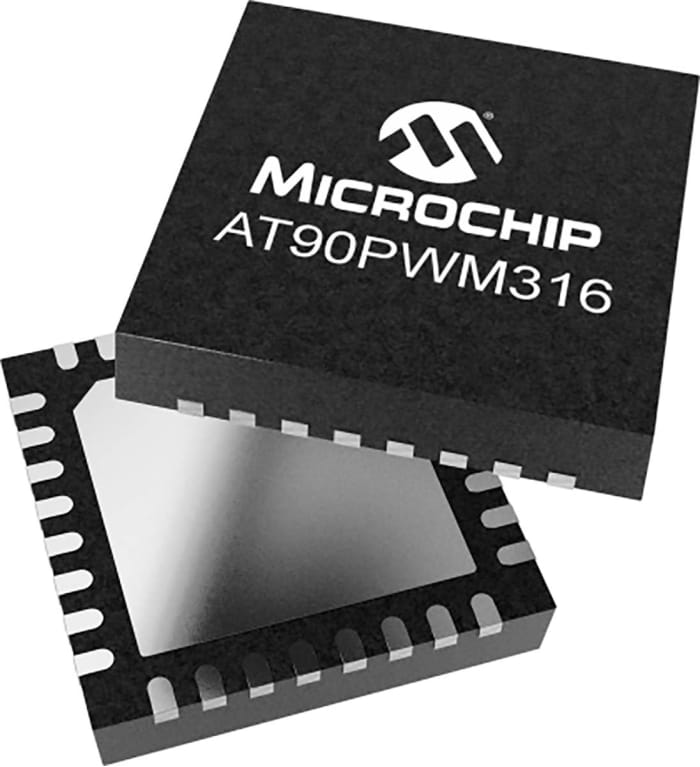
The Microchip AT90PWM316 8-bit microcontroller is based on the AVR enhanced RISC architecture. It operates on 2.7V to 5.5V power supply. The AVR core combines a rich instruction set with 32 general purpose working registers. All the 32 registers are directly connected to the Arithmetic Logic Unit (ALU), allowing two independent registers to be accessed in one single instruction executed in one clock cycle. It features 16K bytes of In-System Programmable Flash with ReadWhile-Write capabilities, 512 bytes EEPROM, 1024 bytes SRAM, 53 general purpose I/O lines, 32 general purpose working registers, three Power Stage Controllers, two flexible Timer/Counters with compare modes and PWM, one USART with DALI mode, an 11-channel 10-bit ADC with two differential input stage with programmable gain, a 10-bit DAC, a programmable Watchdog Timer with Internal Oscillator, an SPI serial port, an On-chip Debug system and four software selectable power saving modes. The Idle mode stops the CPU while allowing the SRAM, Timer/Counters, SPI ports and interrupt system to continue functioning. The Power-down mode saves the register contents but freezes the Oscillator, disabling all other chip functions until the next interrupt or Hardware Reset. The ADC Noise Reduction mode stops the CPU and all I/O modules except ADC, to minimize switching noise during ADC conversions. In Standby mode, the Crystal/Resonator Oscillator is running while the rest of the device is sleeping.

Ideate. Create. Collaborate
JOIN FOR FREE
No hidden fees!


Stock information temporarily unavailable.
€ 675.04
€ 2.596 Each (In a Tray of 260) (Exc. VAT)
260
€ 675.04
€ 2.596 Each (In a Tray of 260) (Exc. VAT)
Stock information temporarily unavailable.
260
Ideate. Create. Collaborate
JOIN FOR FREE
No hidden fees!
Technical Documents
Specifications
Brand
MicrochipProduct Type
Microcontroller
Series
Microcontrollers
Package Type
VQFN
Mount Type
Surface
Pin Count
32
Device Core
AVR
Data Bus Width
8bit
Interface Type
SPI, UART
Program Memory Size
8kB
Maximum Clock Frequency
20MHz
RAM Size
1kB
Maximum Supply Voltage
5.5V
Number of Programmable I/Os
27
DACs
10 Bit
Minimum Operating Temperature
-40°C
Analogue Comparators
2
Maximum Operating Temperature
85°C
Height
1mm
Length
7mm
Standards/Approvals
RoHS
Width
7mm
Minimum Supply Voltage
2.7V
Number of Timers
2
Instruction Set Architecture
RISC
Automotive Standard
No
ADCs
11 x 10 Bit
Program Memory Type
FLASH
Product Details
The Microchip AT90PWM316 8-bit microcontroller is based on the AVR enhanced RISC architecture. It operates on 2.7V to 5.5V power supply. The AVR core combines a rich instruction set with 32 general purpose working registers. All the 32 registers are directly connected to the Arithmetic Logic Unit (ALU), allowing two independent registers to be accessed in one single instruction executed in one clock cycle. It features 16K bytes of In-System Programmable Flash with ReadWhile-Write capabilities, 512 bytes EEPROM, 1024 bytes SRAM, 53 general purpose I/O lines, 32 general purpose working registers, three Power Stage Controllers, two flexible Timer/Counters with compare modes and PWM, one USART with DALI mode, an 11-channel 10-bit ADC with two differential input stage with programmable gain, a 10-bit DAC, a programmable Watchdog Timer with Internal Oscillator, an SPI serial port, an On-chip Debug system and four software selectable power saving modes. The Idle mode stops the CPU while allowing the SRAM, Timer/Counters, SPI ports and interrupt system to continue functioning. The Power-down mode saves the register contents but freezes the Oscillator, disabling all other chip functions until the next interrupt or Hardware Reset. The ADC Noise Reduction mode stops the CPU and all I/O modules except ADC, to minimize switching noise during ADC conversions. In Standby mode, the Crystal/Resonator Oscillator is running while the rest of the device is sleeping.
Ideate. Create. Collaborate
JOIN FOR FREE
No hidden fees!